

IARC Mission 7 Technical Postmortem 2017
During the 2016-2017 academic year the Robotics and Automation Society at the University of Pittsburgh designed and built a drone to compete in Mission 7 of the International Aerial Robotics Competition. The team competed at the American venue and was awarded “Best System Design” and achieved the highest score at the venue.
This post will explore from a technical perspective the current capabilities of 2017’s entry, the overall design of the system, and the challenges facing the team in the 2017-2018 academic year.
Current Capabilities:
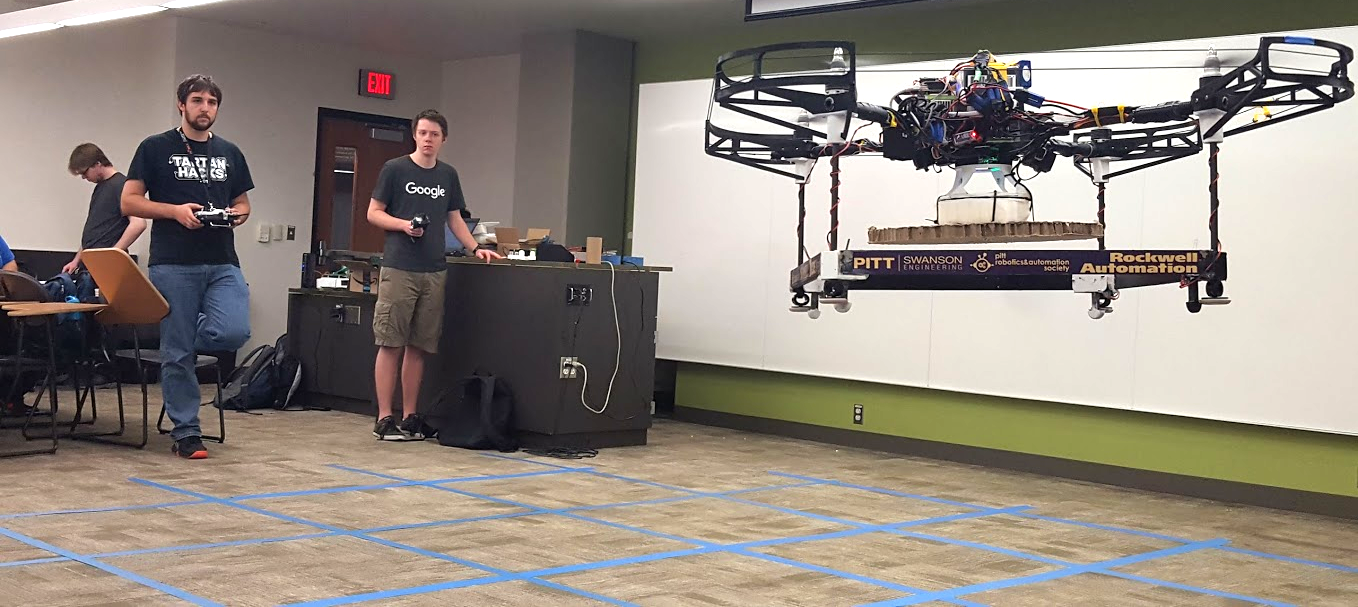
The drone is currently capable of estimating its absolute position in the vertical direction and its absolute horizontal velocity. We are capable of reliable and controlled autonomous takeoff and landing as well as horizontal translation under velocity control. Velocity control allows us to fly pseudo-waypoints (requesting a velocity for an amount of time, but with no absolution positional correction), and we have demonstrated both of these many times at home and at the competition. The drone is also capable of detecting obstacles and ground robots, although these were not demonstrated at competition. Other high-level behaviors such as absolute localization and waypoints based on the grid, and tracking and landing on ground robots, have been tested successfully in a simulator but not on a real-world system.
Official autonomous flight at competition
System Details:
Mechanical:
The 2017 drone was designed to be crash resilient, easy to repair, and easy to modify. Additionally. the team’s most constraining factor in constructing the frame was time. As a result a simple frame was designed that traded elegance for ease of construction and structural testing for overbuilt and heavy parts. Fully assembled, the drone is 1.1 meters across and weighs about 5kg (~10lbs.)
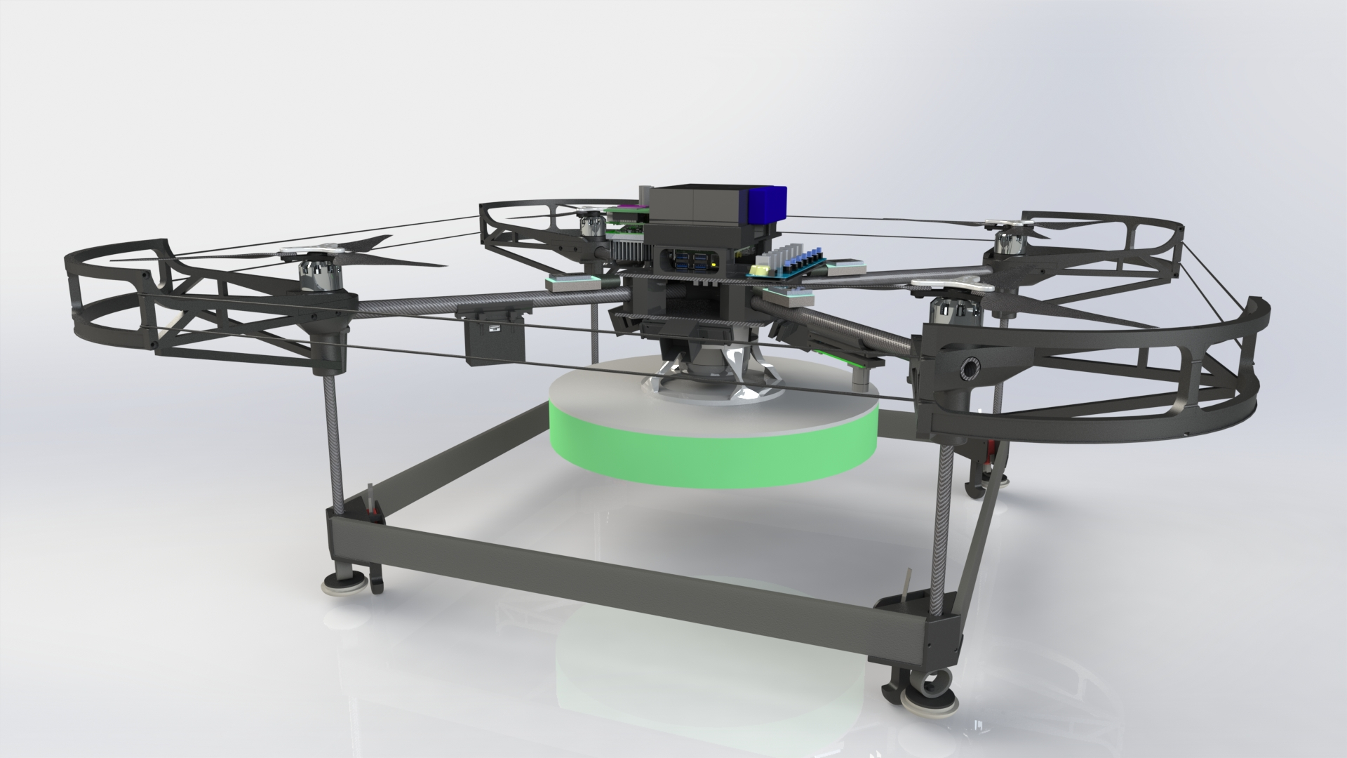
Render of final CAD model
The frame is made primarily out of carbon fiber and 3D printed brackets. Two carbon fiber plates are used in the center of the drone to hold various electronics. 3D printed brackets connect the center plates to the carbon fiber crossbars. At the end of the crossbars the prop guard and motor mounts attach using a pressure fit. The lower bumper bars are attached to the prop guards using carbon fiber tubes. The side bumpers are made out of wood and the green button pushing pad is made out of a low density foam. Not pictured, is a firm cardboard piece that attaches to the bottom of the low density foam. Shielded copper wire is strung around the outer perimeter of the prop guard to form a 360 degree perimeter around the drone.
The team chose to make extensive use of 3D printing for two main reasons: rapid prototyping and the ability to easily design parts that would fail in a desired manner. We found that 3D printed parts could be strategically designed so that when force was applied in an undesired direction they would fail but while be used as intended remained quite strong. Using this property a frame was designed that strategically broke to protect expensive electronics and carbon fiber parts. This design choice saved the team a lot time and money since initial flight testing resulted in many crashes. In most circumstances, replacing a 3D printed part only takes a few minutes. If a severe crash occurs it only takes a couple hours to rebuild the entire frame.
In our testing we found that the prop guards and boundary wires were extremely capable. If the drone accidentally hit a wall or other object it would bounce off of it without damaging the rotors or the prop guards. One disadvantage is the weight that fully 3D printed prop guards bring. This year it was worth the tradeoff, however using a different material would result in significant weight savings.
An interesting mechanical problem was the construction of the landing gear. Significant impact needed to be absorbed in the case of a rough landing and the software team needed mechanical limit switch on each foot for control purposes. Additionally, if the drone hit the ground with a horizontal velocity, as could happen when landing on top of a roomba, the resulting torques on the needed to be controlled.
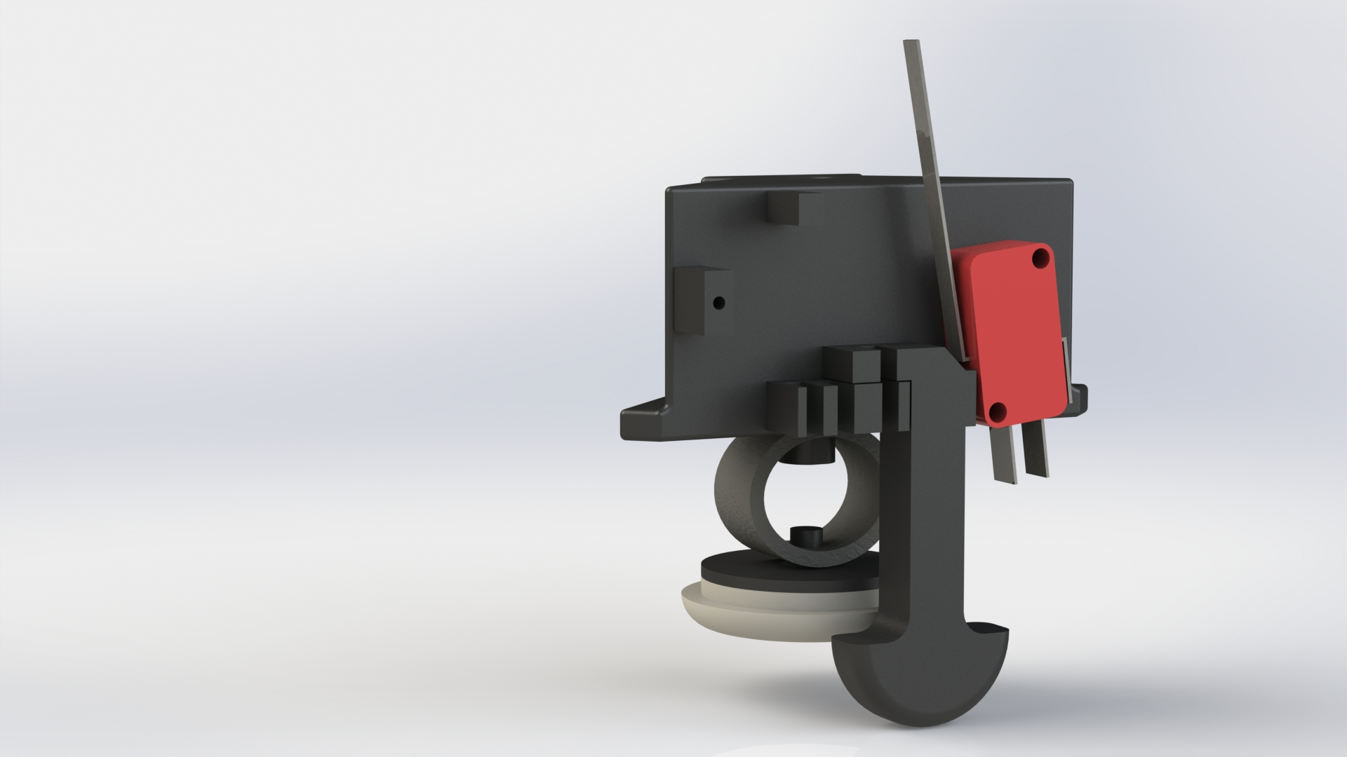
Landing gear system
The image above shows how the three major concerns were integrated into a single unit. To limit the force delivered to the frame in the event of a rough landing a rubber sprint was put between the frame and the ground. To avoid excessive moments in the case of a landing with horizontal translation a carpet slider was mounted to the bottom of the spring. Finally, the limit switch was actuated with a plunger design that allowed for easily settable pre-travel and more than enough overtravel. Not pictured is a rubber band that pulls the plunger back down after it has been pressed.
Electronics:
There are three separate electrical systems on the drone. The high voltage electronics, high voltage monitoring system, and the low voltage electronics. The high voltage electronics includes the motors and ESC’s. They are controlled by the high voltage monitoring system which has the ability to disable power to the ESC’s and motors and measures the motor battery voltage. The low voltage electronics includes the flight controller, computers, and sensors. Communication between the high and low voltage electronics is done over an opto-isolation barrier. This helps ensure that transients from the motors and ESC’s cannot damage the expensive sensors and computers.
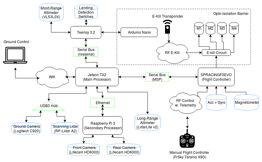
Overview of electrical systems
The drone uses a Seriously Pro Racing F3 EVO for the flight controller. This type of flight controller is commonly used for racing drones. It contains the IMU used to determine the drone’s orientation and is capable of controlling the drone’s orientation. It receives throttle and orientation commands over a serial link with our main control computer.
The main control computer is a NVIDIA Jetson TX2. It receives an image from a downward facing camera through usb, a point cloud from the RP-Lidar A2, height estimates from two different time of flight range sensors, signals from landing detection switches, side camera image feeds from a raspberry pi, and a motor battery voltage supplied by the arduino nano over the opto isolation barrier. The entire software stack runs the Jetson TX2 and it communicates debug data back to a ground station using wifi.
Software:
The software system is built using ROS, and is running on a NVIDIA Jetson TX2 and a Raspberry Pi. We have a variety of ROS packages that we have written ourselves, as well as some others that we have forked and modified for our purposes. The majority of our code can be found on GitHub, and the iarc7_common repository is a good place to start if you’re interested in poking around. This code is open source and free to use under the GPL, but we do ask that other IARC teams using this code or ideas taken from it cite the Pitt Robotics and Automation Society and do not present the work or the ideas contained within it as their own.
Software engineering was taken seriously by the software team to ensure that a system as complex as IARC could be managed. We ended up designing a software stack that maintains abstractions between all major components, contains a built in failure recovery system, and allows for switching between controllers and planners in a safe and controlled manner during flight.
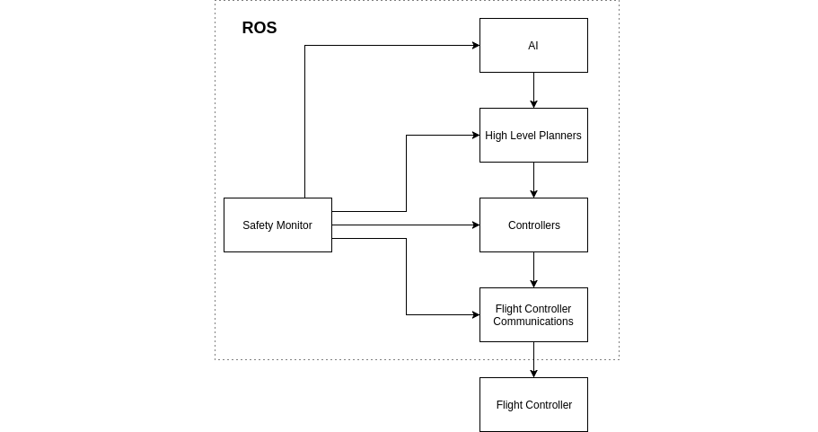
High level relationship between major software components
Illustrated above is general approach taken when designing the software stack. Not pictured, is the various sensor nodes and filters. Each component pictured was abstracted into separate nodes and ROS packages. This allowed us to choose different programming languages for different parts of the system. Additionally, it made it harder to break the abstractions set in place so that junior programmers could not turn the stack into spaghetti.
Boundaries between the responsibilities of nodes allowed us to create a safety monitoring system that allowed for clearly defined safety procedures in the event of a node crashing. On startup nodes connect to the safety monitor. The monitor has a list of nodes that should connect on startup and an order in which safety responses are requested of nodes in the event of failure. Should a node crash or exit, the safety monitor will notify the next node in the chain of command to take an appropriate safety action. For instance, if the high level planner crashes the safety monitor will notify the controllers that they need to attempt a safety response. The controllers will then attempt to descend downward with a set velocity in a stable manner. In practice this system has allowed the drone to recover from unexpected software errors and land safely.
Remaining Problems:
The amount of lift that we are currently able to get out of our propulsion system is only approximately 130% of our weight. Because all of our weight is concentrated in the center of the drone, we are still able to be fairly agile in the pitch/roll direction, but the drone has problems controlling its yaw, especially in windy conditions or in confined spaces where prop wash becomes an issue. The yaw problem is not helped by the fact that the motors are mounted on circular carbon fiber tubes, which provide no reference to keep them vertically aligned. This means that there is always some torque in either the clockwise or counterclockwise direction that the yaw controller must compensate for.
The ground contact switches are very helpful for our takeoff controller, but they have not been perfectly reliable. We believe that a mechanically simpler design based on pressure sensors would be much more reliable.
There were several bugs in the grid detection software which prevented us from running it at competition, but those should be straightforward to fix, giving us full absolute position estimates.
There were issues with the firmware on the first batch of cameras we ordered that prevented us from using them at competition. This meant that we were only able to use two side cameras, and those cameras were streamed through a Raspberry Pi instead of directly into the TX2. On the downward-facing camera which was streamed directly into the TX2, there was a 300ms latency between the time that they were captured by the sensor and the time that they were available for processing. We did not have time to diagnose this problem. All of this means that we will need an entirely different camera setup for next year’s drone.
Our obstacle detection solution is based on a 2D scanning LIDAR, which is fundamentally flawed in that it only detects obstacles in the plane of the scanner. For 7a, this means that we can’t detect obstacles when we are flying above them; for 7b, this means we have almost no hope of detecting the other team’s drone. In the future, we would like to move to an obstacle detection solution which gives us full coverage in all directions.
We have run into several problems related to our software pushing our CPU too hard. First, when our CPU usage gets high (but not 100% on all cores), we occasionally have problems with certain ROS messages timing out. We believe this is due to certain processes not being scheduled as often as they should be, which would only be solved by either switching to a CPU with plenty of extra computational power or switching to an RTOS.
There have also been problems with some of our software simply requiring more computational power than the TX2’s CPU can deliver. While all of these issues could be solved by writing some CUDA code, this isn’t feasible to do for everything, especially for libraries that we didn’t write ourselves. Examples are the obstacle detection code and the EKF we use for localization, which do large amounts of number-crunching on the CPU.
We do not yet have solutions for either reliable ground robot detection with side cameras or for an AI capable of completing the mission; these will have to be developed next year.