

IARC7 Update November 27 2016
This is the first blog post to document the progress of the IARC Mission 7 team. Work began early in the Fall 2016 semester. We have an interdisciplinary team primarily consisting of students of mechanical, electrical, computer engineering, and computer science. This update will be structured to show progress of our primary subsystems.
Mechanical
The team is in the process of designing and building a custom airframe designed to meet IARC 7’s needs. All components are being modeled using the CAD tool Solidworks.
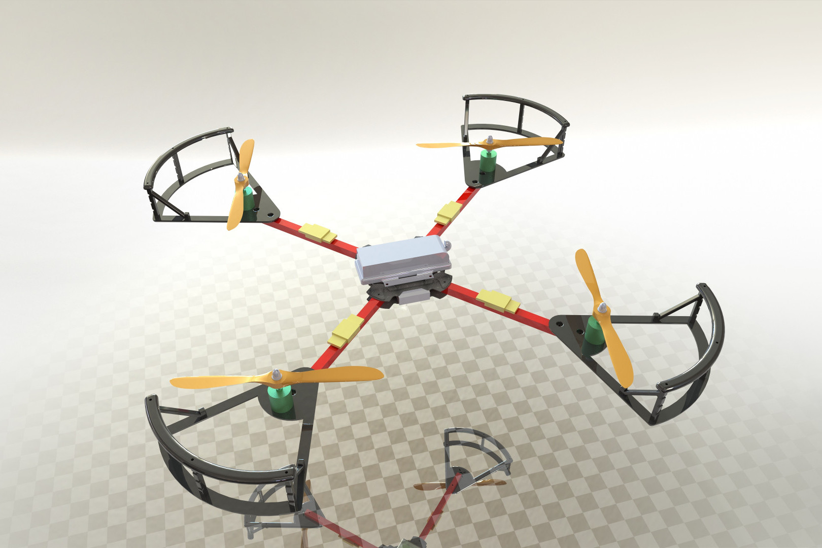
Two versions of the airframe are planned.
The first (V0.1), has been based off the commonly available X525 quadcopter frame and will be used to demonstrated proof of concept of our critical mechanical systems such as landing gear, prop guards, and mounts for the electronics. We are 3D printing a large majority of the components for V0.1 in order to encourage rapid development cycles.
The second version (V1.0), will be based on the first and is not intended to be a complete re-design. The goal is to fix mistakes made in the design of the first airframe while also using materials more suited to the strength and weight needs of our application.
Landing Gear
A design consideration has been to make landing gear capable of safely supporting the aircraft when dropped from the maximum flight height of three meters.
The idea of 3D printed landing gear made of a flexible filament was examined. In order to determine the spring constant of the material, an experiment was devised to find the spring constant of rectangular beams printed with material. Simulations were then run with the material properties using a 4kg load dropped from 2 meters. The results are covered in this blog post.
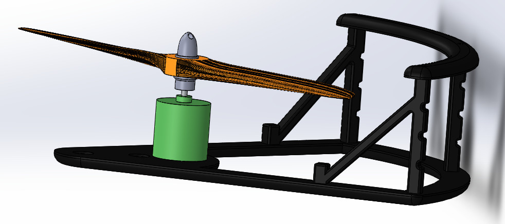
Propeller Guards
The X525 frame does not come with prop guards,so custom guards have been designed. Maintaining a low weight and high guard coverage were the primary focus. To help with this the prop guards were designed to follow a spoke like structure instead of a solid covering. Additionally it was designed so that steel string (not pictured) could be wrapped around all outer edges of the quad preventing entry of object into the airframes perimeter from the side.
Electronics
Safety circuit
Adapting the safety switch from the official website http://www.aerialroboticscompetition.org/downloads/killswitch.zip
We decided to fabricate a replica safety switch using SMT components. A second RC controller seperate from the flight controllers RC controller will be used to controll the safety switch circuit.
Power Delivery
A prototype wire harness for the system’s computers and controllers was fabricated for the initial version. The harness was designed to allow separate power sources for the control electronics and motors. This way, voltage spikes or sages on the motor power bus will not affect our computers or sensors.
Software
We decided to use ROS for our software stack because it provides several useful algorithms that are already implemented, along with modularity and easy simulation. All of our software is running on an NVIDIA Jetson TX1, which has a powerful enough CPU and GPU to allow us to run everything onboard at the moment.
Simulator
The MORSE simulator allows us to test most of our software independently of our hardware. The simulator has physical models of all the iRobot Create targets and obstacles that move as they will in competition, and has simulated sensors that feed data into all of our higher level nodes. It can also send renders of the simulated world to our computer vision algorithms.
FC_Comms
One of the first nodes written is used to communicate with your flight controller. The flight controller selected for V0.1 was a Flip 32+ running the cleanflight firmware. Cleanflight allows communication over an rs232 serial link using the MultiWii Serial protocol.
This node allows throttle, orientation requests, current orientation, and other information to be passed between the flight controller and the Jetson. The node handles receiving information from ROS topics and rebroadcasting them to the flight controller while also broadcasting the flight controllers sensor readings onto ROS topics. Currently this node is 90% functional, all that remains is to connect it to the software safety subsystem when that is ready.
Motion Control
We have several layers of motion control nodes. At the top we have a multiplexer that takes in commands from various different locations, such as our target tracking algorithm and our main control panel. This then feeds a single command into the motion planner, which takes obstacles into account and generates a desired velocity to the quad to travel at to reach its target. At the lowest level, we have a controller based on PID with feed-forward that is capable of holding a specified velocity, which feeds outputs to the FC Comms node. All of these nodes are currently in different stages of the development process.
Altimeter
The Lidar-Lite v2 rangefinder gives us reasonable accurate altitude estimation. We have a single node which communicates with the sensor over I2C, accounts for the quadcopter’s orientation to adjust the readings, and runs a moving average over the signal. The node currently works, but more investigation is needed to determine if a better filter would be useful.
Battery
The V0.1 copter will have multiple batteries. One for the motors and flight controller, and another for the more sensitive electronics like the Jetson and cameras. The flight controller handles reading the motor battery voltage level and communicates it back to the Jetson using FC comms. The Jetson’s battery level is being measured using onboard ADC’s on the developer kit carrier board. See here for more details https://devtalk.nvidia.com/default/topic/950341/jetson-tx1/jetson-tx1-ina226-power-monitor-with-i2c-interface-/post/4998393/#4998393