

IARC7 Landing Gear Design Update November 27 2016
Purpose
Design landing gear capable of supporting impact for a 4kg drone dropped from a height of 2 meters while minimizing shock.
Design Concept – Cantilever Beam
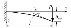
A deflected beam acts like a spring and absorbs energy. This principle was the key idea behind the first landing gear design. Below is a diagram of a cantilever beam fixed on the left end, with a load “P” applied on the right end. Note the maximum deflection is at the tip of the beam on the right.
Applying this concept to drone landing gear, the cantilever beams are legs on the bottom of the drone which deflect from resultant force of impact to absorb the energy as illustrated below.
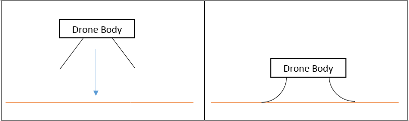
Therefore, to achieve the goal of dropping a drone without causing damage, the landing gear must be designed to absorb the energy from the drop.
Analysis Part 1 – Energy Balance
The potential energy from the falling drone is given by equation 1 below:
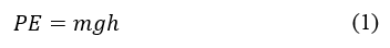
Where “m” is the mass of the drone (2kg), “g” is the gravitational constant (9.81m/s2), and “h” is the height (2m) the drone is falling from. With the cantilever beam design, the energy will be stored as the beam deflects on impact like a spring. The energy stored in a spring is given by equation (2).
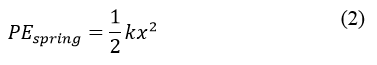
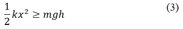
Here “k” is the spring constant and “x” is the deflection of the spring. For the landing gear design to pass the first criteria the potential energy able to be stored in the deflecting beam must be greater than or equal to the potential energy the drone has before falling. That inequality (3) is given by combining equations (1) and (2).
Material Selection
In order to keep a low cost, maintain geometric design freedom, and rapidly prototype we decided to go with 3D printable plastics. An off brand filament with similar properties to NinjaFlex was chosen over ABS and PLA because it has a greater flexibility.
Finding the Spring Constant “k”
The spring constant “k” comes from Hooke’s law shown below.
Where “F” is the applied force, “k” is the spring constant, and “x” is the deflection of the spring. Rearranging equation (4) the spring constant can be calculated with equation (5) if the applied force and deflection are known.
Note: The spring constant for a cantilever beam of uniform cross section can be calculated if the elastic modulus is known and the second moment of inertia can be calculated. Due to previous design choices both of these values were unavailable. The elastic modulus for the chosen off brand filament could not be found and the infill geometry chosen to reduce part weight made the calculation for the second moment of inertia difficult.
Therefore, the spring constant for our initial landing gear design was measured experimentally. Cantilever beams were designed in SolidWorks and the infill percentage and shape was set with the slicer.
Three different beams with the same external dimensions and unique infill percentages were tested and a spring constant was calculated for each. They were each loaded with three different weights and at each weight the deflection of the beam was measured. A plot of the results can be seen on the following page.
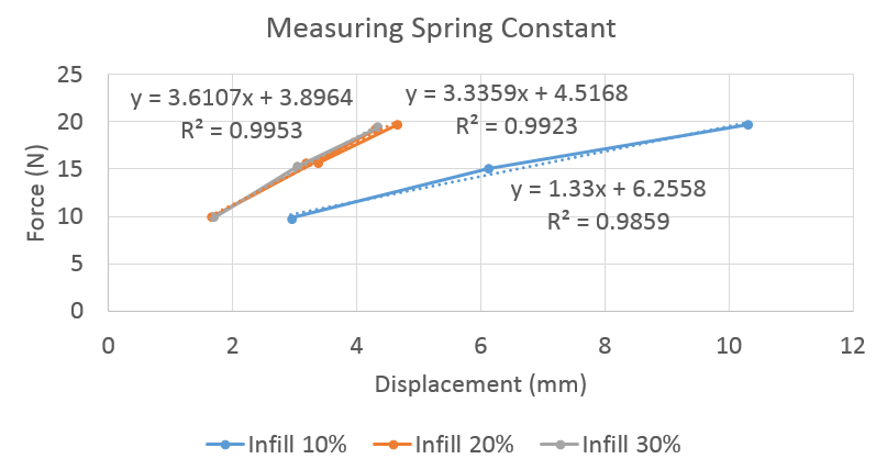
The test showed that the deflection appeared to vary linearly with the applied force. The slope of each line above is the measured spring constant for that particular beam (in N/mm).
Analysis Part 2 – Beam Deflection
With the measured spring constants from the previous section the theoretical deflection of our cantilever beam on impact can be calculated. Turning the inequality (3) into an equality and solving for displacement yields the necessary equation.
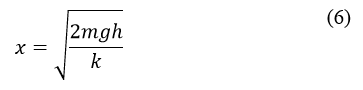
Using the stiffest cantilever beam’s (30% infill) spring constant (3.6 N/mm) and equation (6) the deflection of the beam required to absorb all the energy from the proposed drop was calculated to be 0.217m. The required deflection was greater than our test beam length of 100mm.
The beam could be lengthened to allow for this deflection, but the spring constant “k” would then decrease with the cube of the length “l” as shown by equation (7).
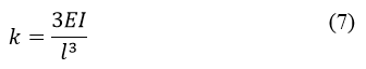
The elastic modulus “E” is a fixed material property, however the second moment of inertia “I” is solely dependent on the geometry of the beam. The decrease in spring constant “k” caused by increasing beam length “l” could be compensated for by increasing the second moment of inertia “I”. Increasing the infill percentage or increasing the cross sectional area of the beam would both increase the second moment of inertia.
Weight Concerns
Adding weight to the drone decreases flight time and reduces our maneuverability and is therefore undesirable. To absorb the energy of the drone impact, the tested beams would need to be longer, denser, and have a larger cross sectional area; ultimately they would be much heavier.
Conclusion
The energy analysis showed that the present design for cantilever beam landing gear would not absorb the impact of the drone. While the landing gear geometry could be changed to provide a design that would absorb the impact, the increase in weight due to the geometric is a significant concern.
Recommendations
Explore other landing gear options such as metal spring and damper. Lower the required drop height from 2m to a lower value such as 0.5m or less.